HDI board, high density interconnect printed circuit board
HDI boards are one of the fastest growing technologies in PCBs and now available in ABIS Circuits Ltd.
HDI boards contain blind and/or buried vias, and usually contain microvias of 0.006 or smaller diameter. They have a higher circuit density than traditional circuit boards.
There are 6 different types of HDI PCB boards, from surface to surface through holes, with buried holes and through holes, two or more HDI layers with through holes, passive substrates without electrical connection, using layer pairs The alternating structure of the coreless structure and the coreless structure uses layer pairs.


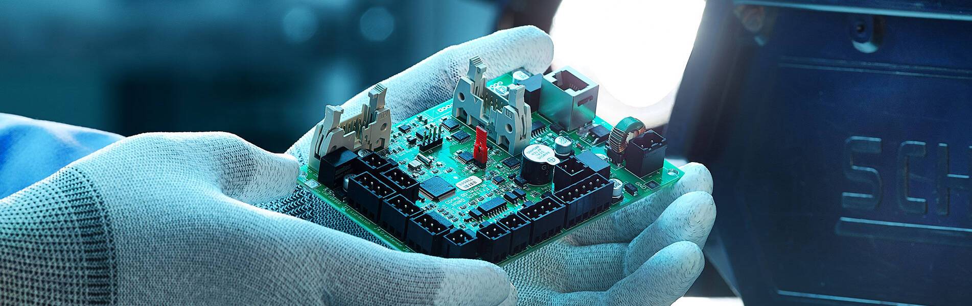
Printed circuit board with HDI technology
Consumer Driven Technology
The in-pad via process supports more technologies on fewer layers, proving that bigger is not always better. Since the late 1980s, we have seen camcorders use novel-sized ink cartridges, shrunk to fit the palm of your hand. Mobile computing and working at home have further advanced technology, making computers faster and lighter, allowing consumers to work remotely from anywhere.
HDI technology is the main reason for these changes. The product has more functions, lighter weight and smaller volume. Special equipment, micro-components and thinner materials enable electronic products to shrink in size while expanding technology, quality and speed.
Vias in the pad process
Inspiration from surface mount technology in the late 1980s has pushed the limits of BGA, COB, and CSP to a smaller square inch. The in-pad via process allows vias to be placed in the surface of the flat pad. The through holes are plated and filled with conductive or non-conductive epoxy, then covered and plated to make them almost invisible.
It sounds simple, but it takes an average of eight additional steps to complete this unique process. Professional equipment and well-trained technicians pay close attention to the process to achieve perfect hidden through holes.
Via filling type
There are many different types of through-hole filling materials: non-conductive epoxy, conductive epoxy, copper-filled, silver-filled, and electrochemical plating. These will cause the through holes buried in the flat land to be completely soldered to the normal land. Drilling, blind or buried vias, filling, plating and hiding under the SMT pads. Processing this type of through hole requires special equipment and is time consuming. Multiple drilling cycles and controlled depth drilling increase processing time.
Cost-effective HDI
Although the size of some consumer products has shrunk, quality is still the most important consumer factor after price. Using HDI technology in the design, the 8-layer through-hole PCB can be reduced to a 4-layer HDI micro-hole technology package PCB. The wiring capability of a well-designed HDI 4-layer PCB can achieve the same or better functions as a standard 8-layer PCB.
Although the microvia process increases the cost of HDI PCB, proper design and reduction of the number of layers can significantly reduce the cost of square inches of material and the number of layers.
Build unconventional HDI boards
The successful manufacture of HDI PCB requires special equipment and processes, such as laser drilling, plugging, laser direct imaging, and continuous lamination cycles. HDI board line is thinner, the spacing is smaller, the ring is tighter, and the thinner special material is used. In order to successfully produce this type of board, additional time and a large investment in manufacturing processes and equipment are required.
Laser drilling technology
Drilling the smallest micro-holes allows more techniques to be used on the surface of the circuit board. Using a beam with a diameter of 20 microns (1 mil), this high-impact beam can penetrate metal and glass to form tiny through holes. New products have emerged, such as low-loss laminates and uniform glass materials with low dielectric constants. These materials have higher heat resistance for lead-free assembly and allow the use of smaller holes.
HDI board lamination and materials
Advanced multilayer technology allows designers to add additional layer pairs in sequence to form a multilayer PCB. Using a laser drill to create holes in the inner layer allows plating, imaging, and etching before pressing. This process of adding is called sequential construction. SBU manufacturing uses solid-filled vias to allow better thermal management

 Englishen


